-
Detecting and preventing collisions: The earlier the better
Machine damage worst-case scenario: A collision between the machine head and the part, the tool and clamping devices or the spindle and machine table can be an expensive mistake. But even if the worst doesn't happen, detecting and preventing potential collisions almost always results in unintended downtime. This doesn’t need to be the case.
On simpler machines, an attentive machine operator can usually visually detect potential collisions and press the emergency stop button in time. However, fast and complex movements make it impossible to manually interrupt machining on modern high-performance machines like turning-milling centers or simultaneous 5-axis machines. These machines are automatically stopped by integrated protective mechanisms in the event of a collision risk. But even if the machine is stopped manually or automatically, the result is the same: The machine is sitting idle.
To prevent machine downtime, collisions should be detected and prevented before the actual machining begins. There are three different competing solutions that are offered by CAD/CAM and simulation software providers. All three models use digital twins of the real manufacturing environment to verify the toolpaths.
Preventing collisions before machining on the machine: Comparison of models
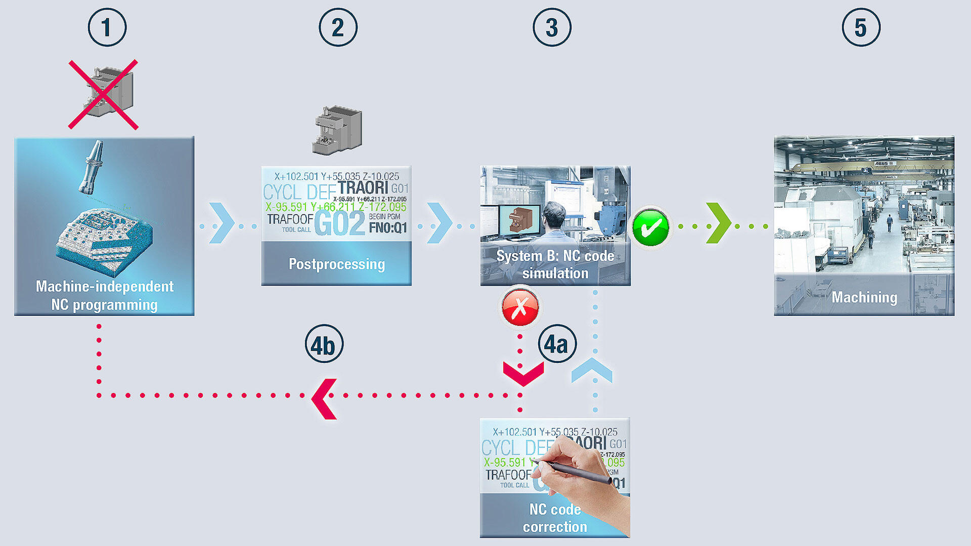
Model 1: With this approach, the NC program is first generated in the CAM environment independent of the machine (1). The postprocessed data isn’t supplemented with the information for the relevant machine until NC output (2). The CAM programmer, the production manager or the machine operator then uses a separate simulation application to verify the NC code.
One of two options is used for managing irregularities: The NC code is manually corrected and then simulated again (4a). For larger corrections, the error is corrected in the CAM environment and then the NC program is output again (4b).
If no other collisions are identified, the part can be machined (5).
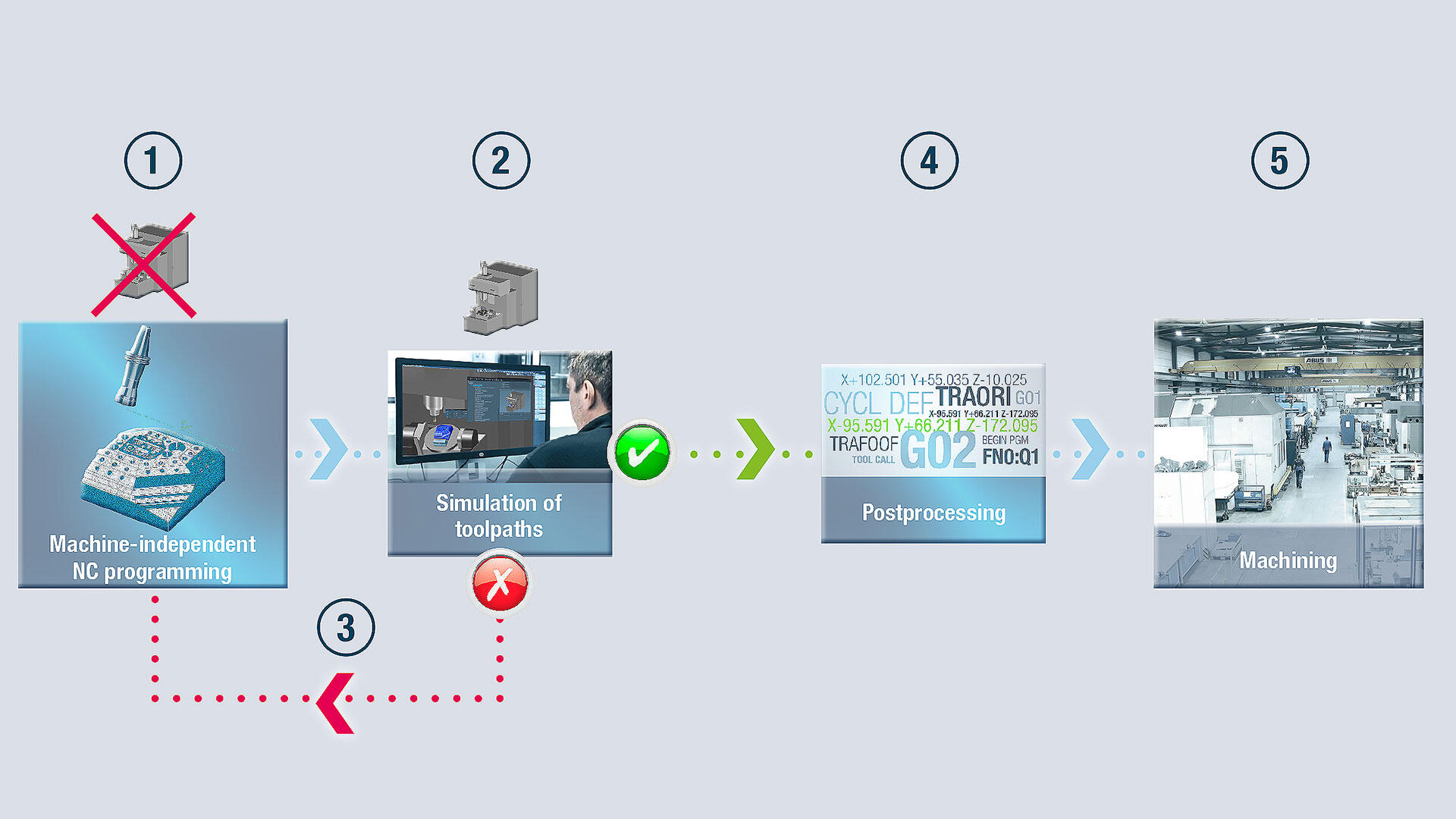
 Model 2: In this approach, the CAM programmer also generates the NC program first, independent of the machine (1). The programs are then verified in the CAM environment and supplemented with the data for the machine that’s being used (2). Potential errors are corrected in the CAM environment (3). The program is then verified again. If no other collisions are detected, the NC code is generated (4) and transferred to production for machining of the part (5).
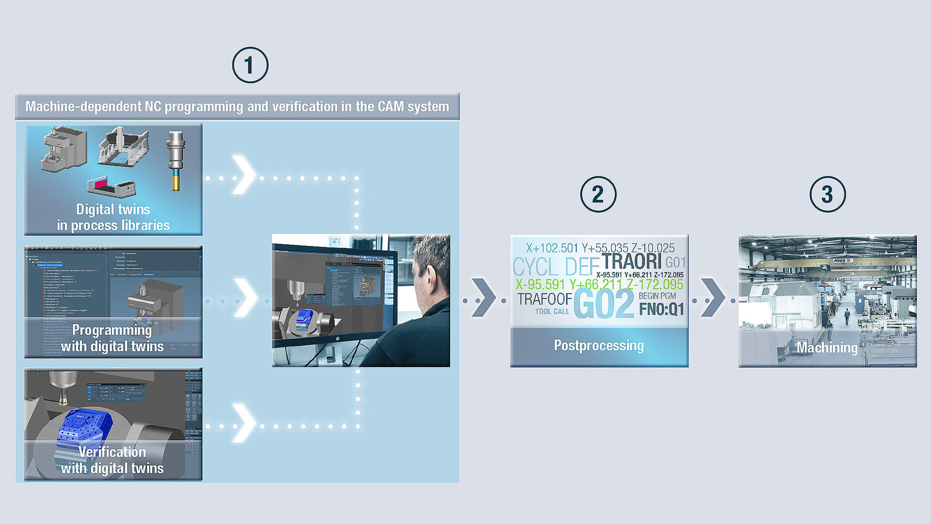
Model 3: In the third approach, planning, programming and verification are performed in the CAM environment with digital twins of the real production environment: The CAM programmer uses all manufacturing-related data from the machines and tools used, checks the machining for collisions right in the system and corrects any errors. (1). This means that the programs that are output are already completely collision-checked (2). The NC code is then sent directly to manufacturing for machining of the part (3).
Model 2: In this approach, the CAM programmer also generates the NC program first, independent of the machine (1). The programs are then verified in the CAM environment and supplemented with the data for the machine that’s being used (2). Potential errors are corrected in the CAM environment (3). The program is then verified again. If no other collisions are detected, the NC code is generated (4) and transferred to production for machining of the part (5).
Model 3: In the third approach, planning, programming and verification are performed in the CAM environment with digital twins of the real production environment: The CAM programmer uses all manufacturing-related data from the machines and tools used, checks the machining for collisions right in the system and corrects any errors. (1). This means that the programs that are output are already completely collision-checked (2). The NC code is then sent directly to manufacturing for machining of the part (3).
This comparison of the three variants shows that the third approach – integrated simulation and collision-checking – has many advantages:
- Additional interface operations and correction loops are avoided.
- It’s simpler, because the CAM programmer doesn’t need any special knowledge of machine code or other simulation software.
- No manual corrections to the NC code that could place process reliability at risk are necessary.
- Planning is easier, because the CAM programmer has access to all the virtual manufacturing components that are represented in virtual process libraries.
- All corrections automatically flow back into the CAM environment, so errors are never repeated.
Not all digital twins are the same
For Model 3 – the fully integrated solution – to also function reliably on complex high-performance machines and machines with special auxiliary equipment, it must be possible to reproduce the real machining situation absolutely precisely in the virtual world with all geometry – including machines, tool assemblies, clamping devices and limit switches. Simplified substitute geometries – like symmetrical and asymmetrical machine heads – aren’t sufficient to serve as digital twins. Kinematic information needs to also be registered: i.e. reference points, tool change positions and traverse movements. This is the only way that a digital twin of the real NC code can be generated in the CAM environment.
A precise virtual representation of the real machining situation requires that all properties of the machine be precisely measured and transferred to the CAM system.Detecting and preventing collisions with the fully integrated solution: planning, CAM programming, simulation
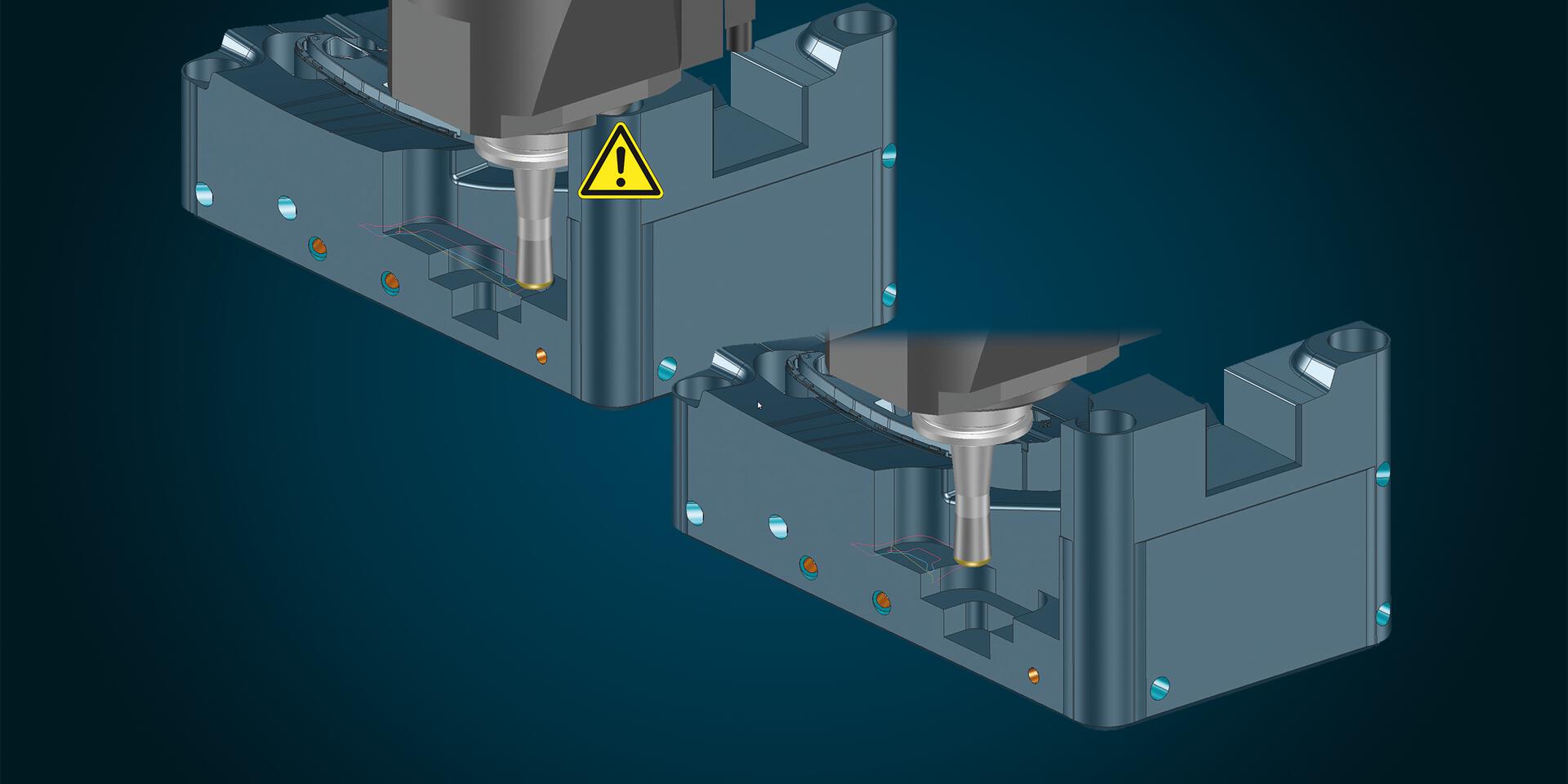
Another advantage of the fully integrated solution: Because the CAM programmer has access to all components that are also used in real production right at his or her workstation, comprehensive options are already available for preventing collisions during planning and CAM programming – i.e., even before simulation. This saves even more time. Many errors are corrected before they can become a problem.
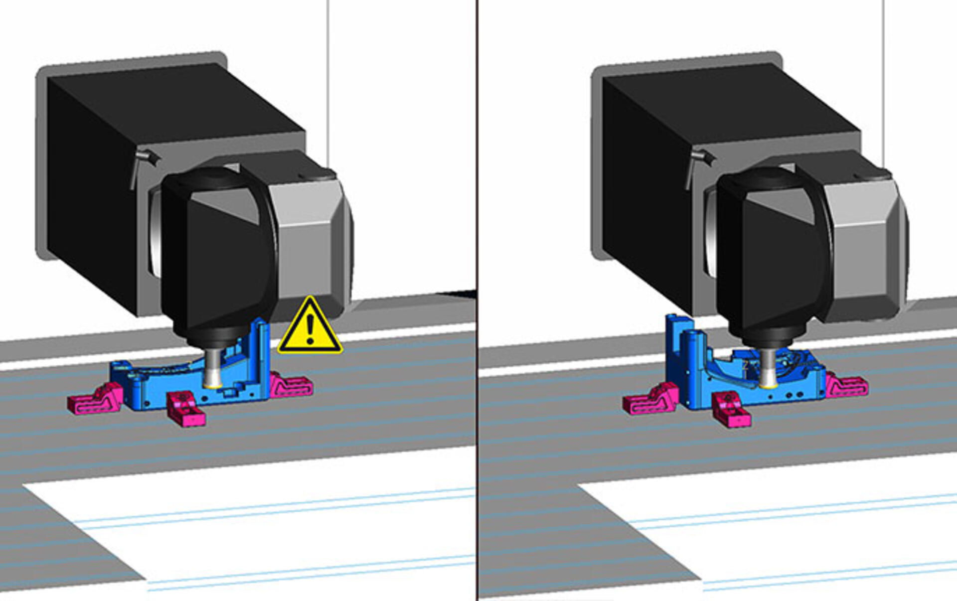
During the planning phase, for example, the CAM programmer moves with the tool clamped to the position that could become critical. If the clamping situation is determined to be impractical due to the head geometry, the table – or in this case the part – is rotated by 180 degrees.
The clamping situation can be optimized early, during work preparation. Collisions are prevented and shorter tools are used for longer periods.CAM programming with intelligent collision avoidance strategies
Collisions that are detected during calculation of the NC program can be identified and prevented with collision avoidance strategies. The most appropriate strategy depends primarily on the specific component geometry, the machining task and especially the available machine. This knowledge should be stored in NC templates: This means that the CAM programmer only has to select the machine and machining elements. The appropriate collision avoidance strategy – with area reduction, simultaneous 5-axis avoidance milling or indexed machining – is automatically assigned.
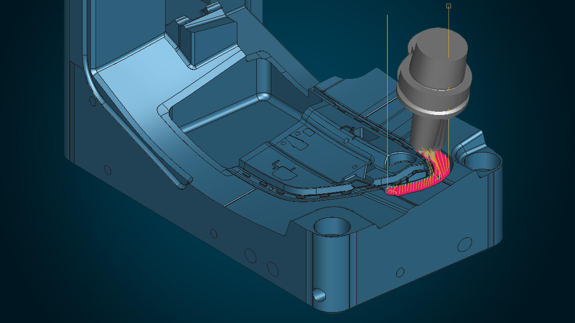
Automatic area reduction is generally used in 3-axis roughing: Milling areas that can’t be machined with the tool in use – because of a collision with the machine head, for example – are automatically deactivated.
Short tools with high cutting values can be optimally used in 3-axis roughing. Therefore, only areas with a collision risk are manufactured using a longer tool.
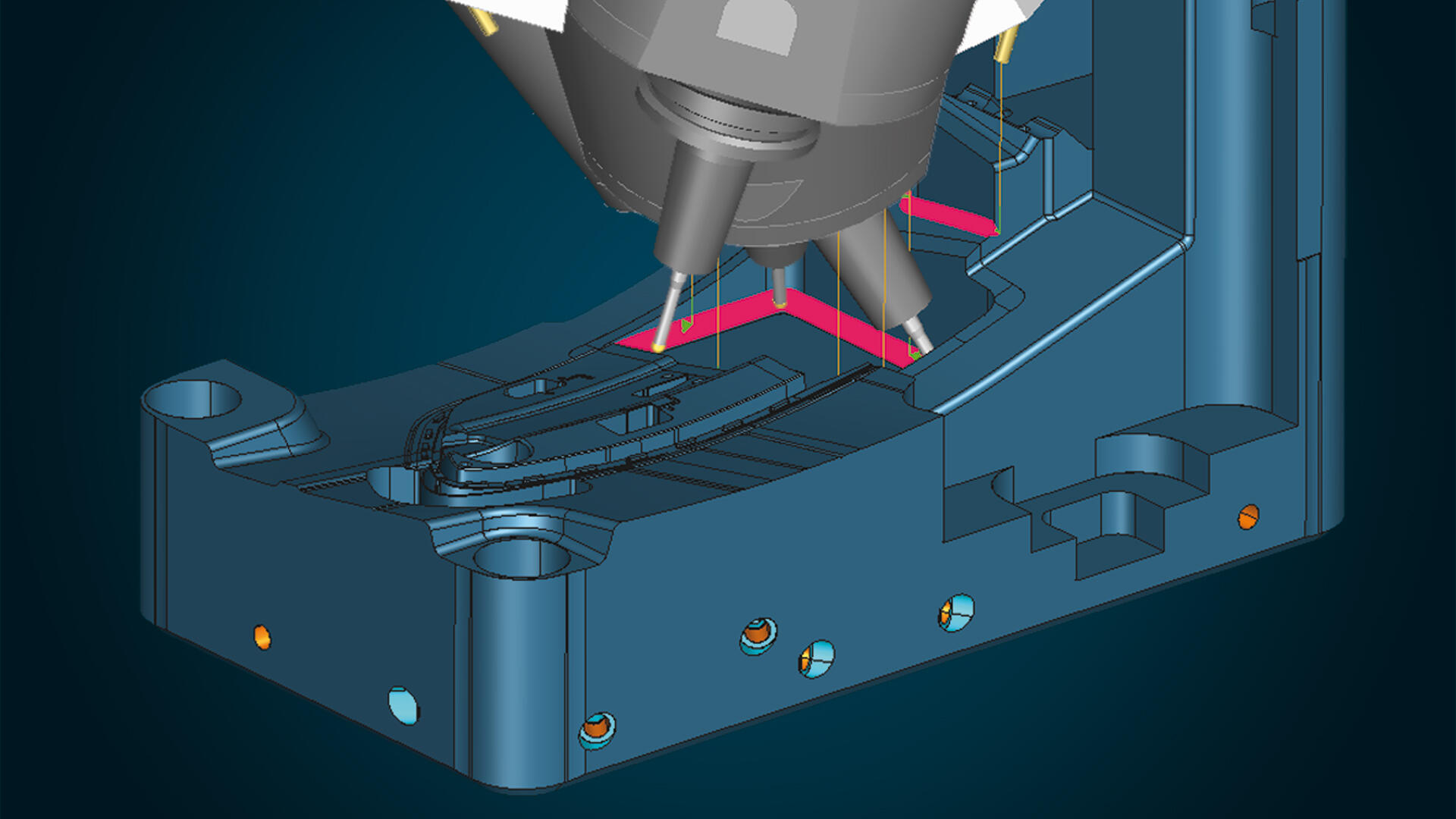
It’s useful in finishing to use a short tool as continuously as possible for the best surface quality. If the machine kinematics permit, 5-axis simultaneous avoidance milling is a good collision-avoidance strategy.
In 5-axis simultaneous avoidance milling, programs for simultaneous 5-axis milling are generated completely automatically from 3+2-axis NC programs with fixed positionable axes.
Machining of residual stock areas is frequently indexed. Indexed collision avoidance is recommended, for example, for multi-axis machines that are unsuitable for 5-axis simultaneous machining because of their dynamics. In some cases, machining performance is even better, and the surface quality is better than when 5-axis avoidance milling is used.
In indexed machining, milling areas that can be machined collision-free at the same tilt direction are automatically detected and combined. The corresponding tilt direction is also automatically calculated.
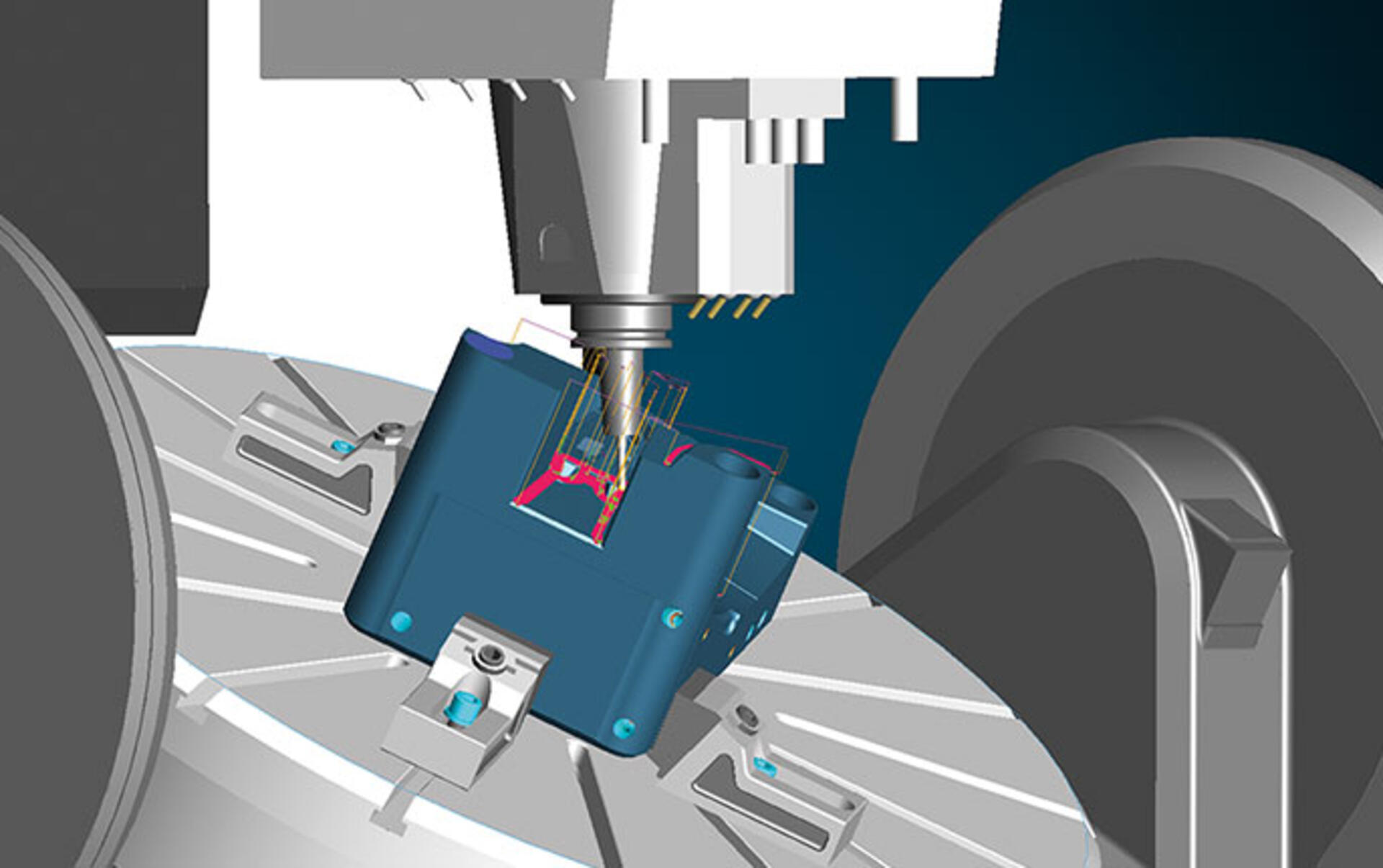
Simulation of the entire machining area
As an extra option, once all strategies have been calculated, the complete manufacturing process can be fully tested with the entire machining area in batch mode. Retract movements can also be individually modified.
Integrated simulation accounts for all tilt directions, all tool components and the entire machine with all movements and tool changes. This ensures that machining is collision-free for each clamping situation.
In summary: The earlier in the process chain that collisions are prevented, the better. This requires that all virtual components be precise replicas of their real twins. This enables the optimal utilization of all options for collision avoidance – from planning and CAM programming to simulation.