Fabriquer sans stresser
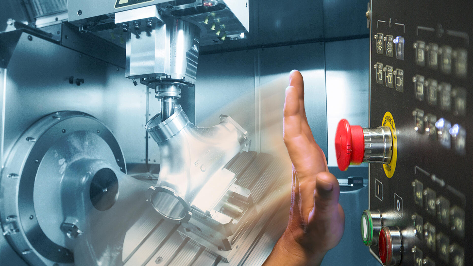
I can still clearly remember the late '90s when I worked as a CAM programmer in my father's mold-making company. We knew if it was going to be a good or bad day within the first five minutes of starting production. At that time, we could really only control the tool and the setup – everything else had to be left to the skill, ability and even the mood of the machine operator that day! There was always a residual risk. We called it "braving the gap." Unfortunately, some collisions resulted.
Much has changed since then. Fortunately, the continuing development of CAD/CAM software and machines means that collisions hardly ever occur anymore.
FAQ: Avoiding collisions
Much has changed since then. Fortunately, the continuing development of CAD/CAM software and machines means that collisions hardly ever occur anymore.
FAQ: Avoiding collisions
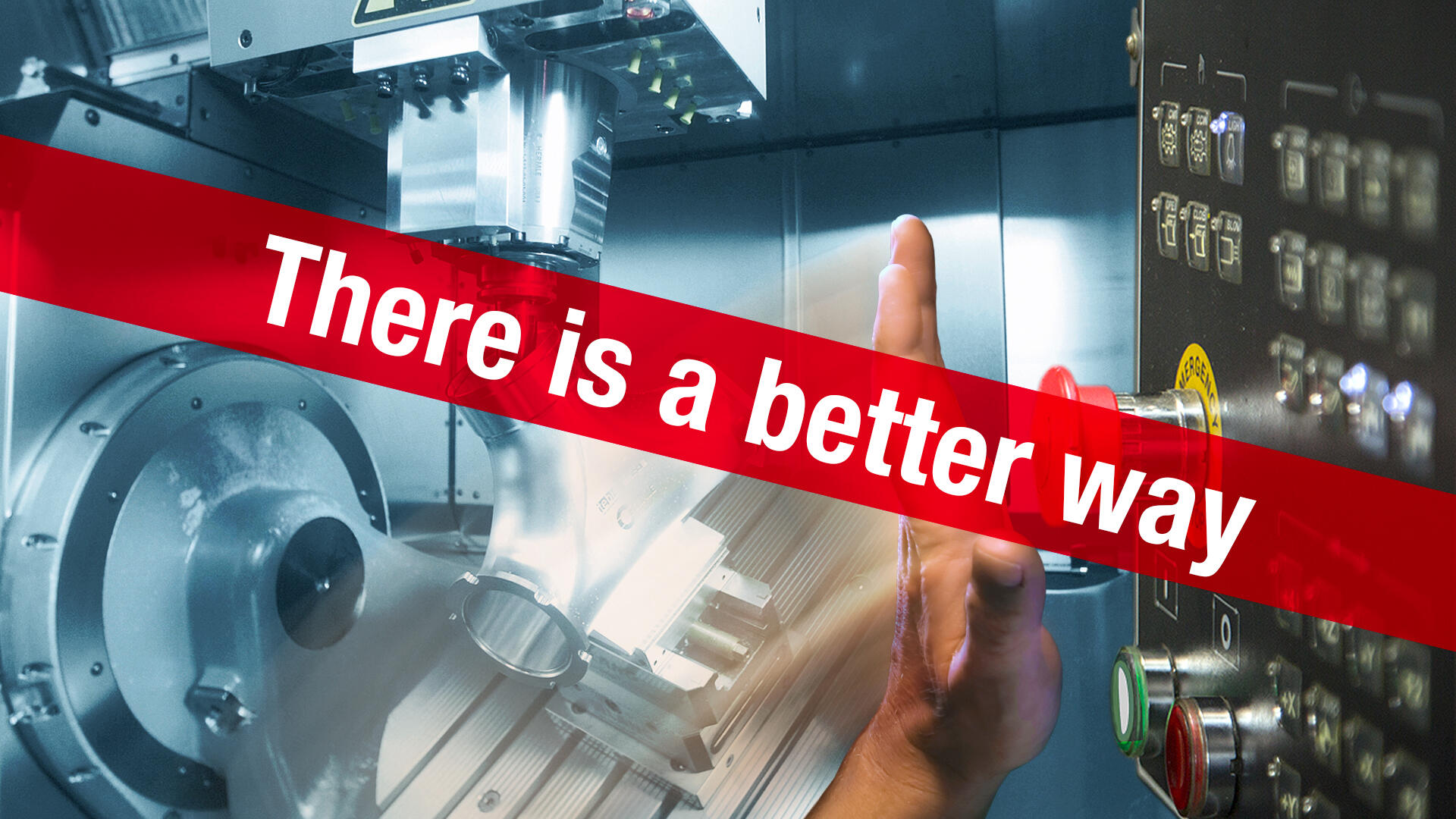
Where workarounds reach their limits
But what’s often forgotten: Collision checking isn’t just about a specific manufacturing situation. The subject of "time" also plays an important role. And the foundation of automation is safety through standardization. Many die and mold manufacturers that I currently visit as a Tebis consultant still rely on workarounds that are admittedly resourceful:
Especially on more complex machines, automatic stop mechanisms in the machine software are relied on to prevent potential collisions.
The problem: The machine still stops. The error must corrected. Every wasted or unused milling hour can no longer be recovered.
Feed rates are reduced and retract movements increase.
The problem: This "fear factor" means that the potential of your resources isn’t fully utilized. In other words, the feed rates enabled by the tool and machine aren’t used and the tool is always retracted more than is necessary for collision-free manufacturing.
In 3-axis machining, the part is continuously manufactured with a longer tool throughout, in the event of a potential collision with the machine head.
The problem: This is at the expense of optimal cutting conditions. Surface quality suffers.
Auxiliary geometries are designed for critical points: Toolpaths are generated from cuts or curves to determine how close the tool can approach.
The problem: This additional work takes a lot of time. A lot of expertise is also required.
Interfering geometries like machine heads are designed manually, or else the spindle is attached to the tool with a rotationally symmetrical body.
The problem: This is also very time-consuming and requires a lot of expertise. In addition, the designed interference geometries are rarely realistic and don’t account for machine kinematics.
It still remains the task of the machine operator to avoid collisions through trial and error!
The problem: This is also very time-consuming and requires a lot of expertise. In addition, the designed interference geometries are rarely realistic and don’t account for machine kinematics.
It still remains the task of the machine operator to avoid collisions through trial and error!
My conclusion
These "workarounds" don’t leave any options open for reduced-personnel manufacturing, 24/7 or targeted planning. Even though they may work, they don’t address the real core of the problem.
My recommendation
Take full control of your manufacturing and learn what’s possible:
- Read our question and answer sheet to get an initial overview along with key suggestions and examples
- For more information, see our free webinar
- Or contact me directly: Call or write to me.
Would you like to learn more? In this webinar you can hear from our experts Fabian Jud and Jakub Dittmar:
- When and where you can prevent collisions along the process chain
- Why it’s best to move collision checking and prevention all the way upstream to the CAM system
- What option you have to prevent collisions in the CAM system
- The advantages and disadvantages of different collision avoidance strategies
- How you can manufacture more safely and reduce your employees’ with automated solutions for collision avoidance
FAQ with important suggestions and examples

- Why should potential collisions be corrected before the part is on the machine?
- What are the variants for advance collision detection?
- Which of these three variants is the safest?
- What manufacturing resources should be represented in the virtual CAM environment and accounted for in the collision check?
- What are the collision avoidance options in the fully integrated solution?
- How are the automated collision avoidance strategies implemented in programming?

Our blog author:

I’ve experienced the world of die and mold manufacturing from many angles over the past 28 years: As a CAM programmer, I wanted to get the best out of the part; as a production manager, I had to keep the entire production chain running; and as a deputy managing director, I was interested primarily in value creation and profitability. Now, as a consultant with a "neutral" outside perspective on internal processes, I help companies survive and thrive in the market: This entails coordinating the ideas of everyone involved in the process, evaluating the special features and strengths of the company and making optimal use of modern operating resources like machines and tools and powerful CAD, CAM and MES software systems.