-
Tebis Version 4.1 Release 3
Fast and convenient
The third release of Tebis 4.1 has made it to the big leagues for its functional improvements and new developments: Shorter programming times with improved NCJob technology, complete collision control accounting for material removal, automatic detection of planar areas – these are just a few of the most important highlights that yield enormous benefits for users in their daily work and that allow them to more quickly and easily reach their goals.
This latest release therefore consistently continues the trend set by Tebis 4.1 – following our motto "Fast and convenient.” As a robust hybrid CAD system with logical and intuitive user guidance, Tebis 4.1 lays the foundation for manufacturing processes that can be automated and that prepare you for the future.
CAD – Parametric design
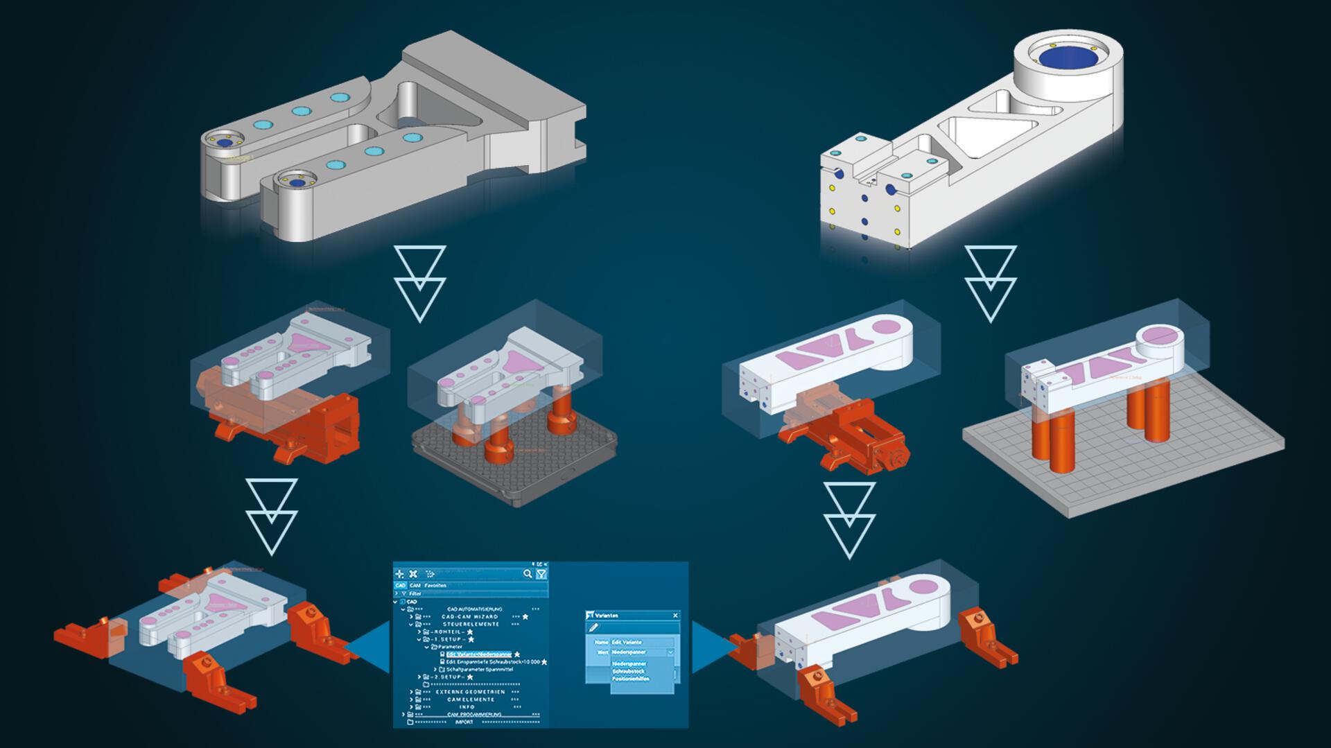
Conveniently control changes with user parameters
Every imported data set needs to be prepared for CAM programming in design. This usually takes many individual work steps: Bores for clamping systems must be placed, tilt axis systems defined, fill surfaces designed, blanks created, connection points for setups generated, clamping devices positioned and retract planes defined. These many individual steps can be highly automated in Tebis using parametric CAD templates. These templates can be extended as needed and can be adapted to meet customer-specific requirements. Users can still be highly flexible: Changes like selecting a different clamping system can now be controlled directly and conveniently with the user parameters in the object tree.CAD – Active surface design
Precise results when trimming deep-drawing and bending parts
The "Create development curves" function can be used to quickly and easily determine theoretically designed trim edges for flanges on deep-drawing and bending parts. The material thickness of the component and the location of the neutral fiber are accounted for – and the result is highly precise, with no manual reworking necessary. The quality of the resulting curves corresponds to that of the original curves.
Multiple calculation modes cover different use cases.CAM – Automation
Shorter programming time thanks to improved NCJob technology
Your CAM programs are finished more quickly with these new features:
Take advantage of the opportunity to automatically apply interactively defined milling areas from previous NCJobs in milling.This allows you to reduce manual intervention in CAM programming and calculate entire NCJob sequences at once. CAM programming is also significantly simplified – you can easily manage combined machining operations in an end-to-end CAM template.
And you can avoid issues like superfluous calculation time by conveniently calculating multiple NCJobs simultaneously up to "Areas calculated" or "Sorting executed" status.
CAM – Drilling
Flexibly use special cutters
 When using combined special cutters with several cutting edge areas of different diameters, only the diameter of the active cutting edge determines whether the tool is suitable for the specific machining task. This enables highly flexible use of special cutters for drill-milling and thread milling in bores and circular pockets – regardless of the diameter of the largest cutting area. The plausibility check also only accounts for the properties of the cutting area actually used.
CAM – Milling
Optimal cutting conditions for roughing rotationally symmetrical parts
Roughing rotationally symmetrical components in a single operation with high stepover and finishing with low stepover.A real plus for combined turning/milling operations: In addition to cylindrical parts, tapered parts such as screw conveyors can now also be machined with high efficiency. The tool first roughs the part to the maximum possible depth with a low stepover and large downfeed in a single pass. Then it machines the residual stock from bottom to top with a smaller cutting depth – precisely to the stock allowance. This procedure reduces tool wear and ensures a high material removal rate on the machine. The user can easily program the final finishing operation with a special function: Only the strategy is replaced – the system does the rest.
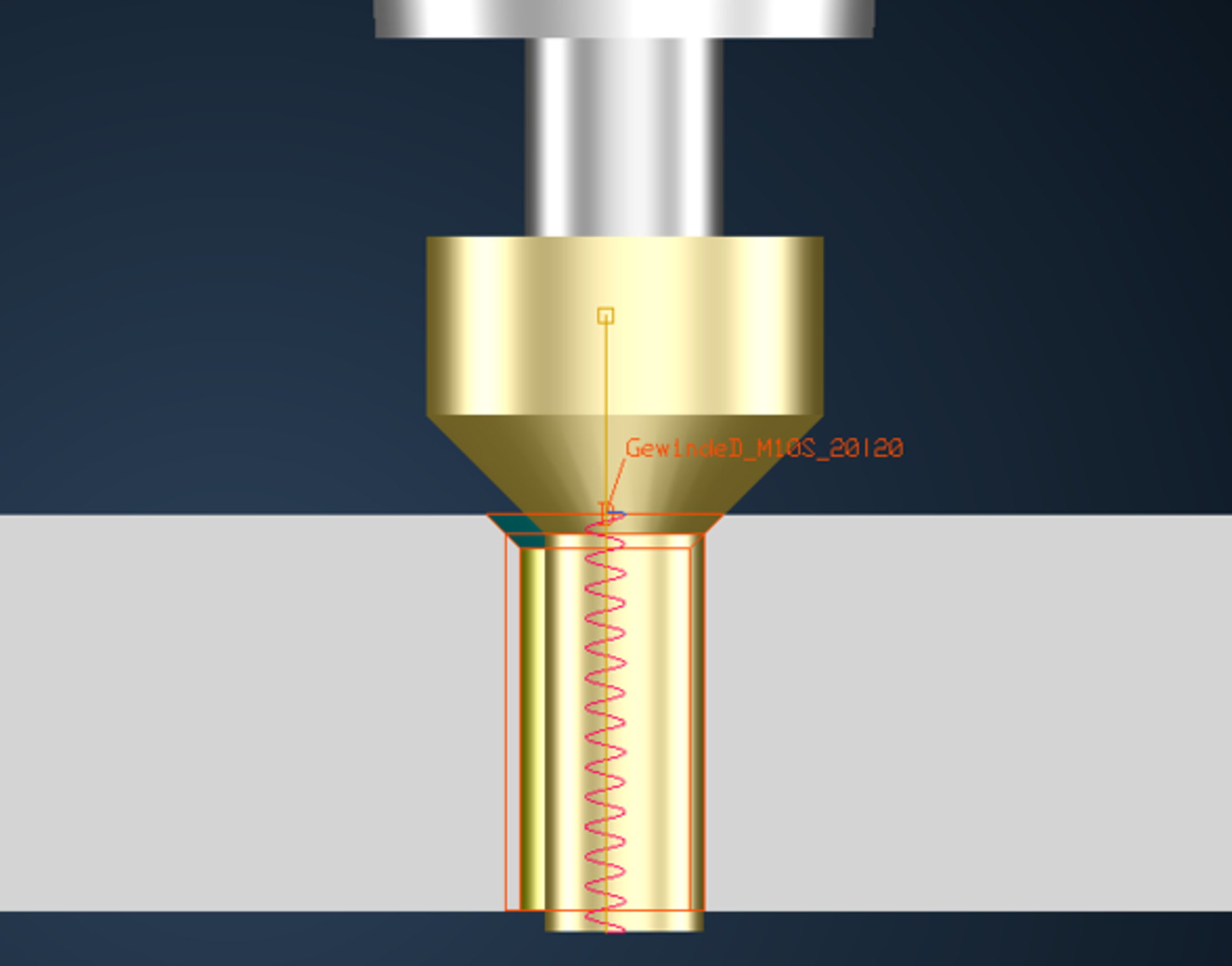
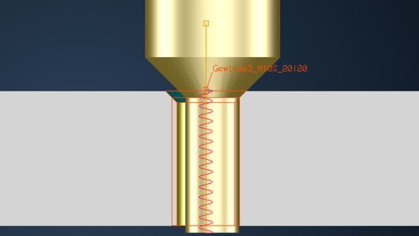
Safely manufacture external threads
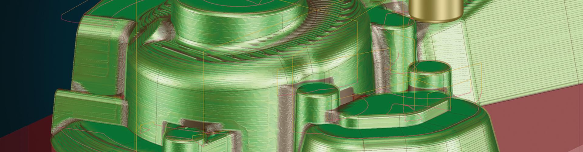
Efficiently machine planar areas
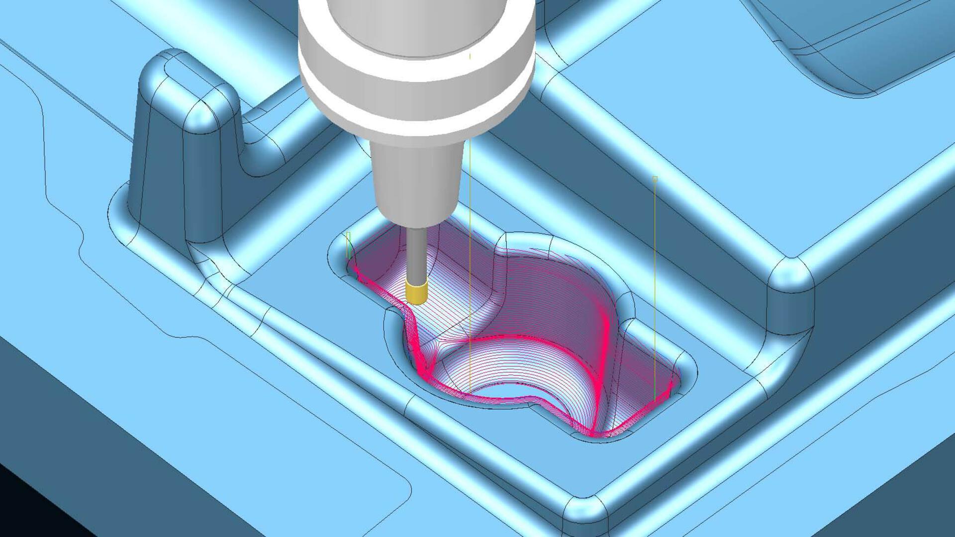
It’s usually more cost-effective to machine the planar areas of a part after hardening with a smaller stock allowance than the non-planar areas Special tool types like large insert mills can then be used for this step. Tebis therefore offers a new function that automatically detects purely planar areas within selected part surfaces without the need to further subdivide the part.Continuous, automated 3-axis finishing of flank surfaces, transition areas and bottom surfaces with no offset
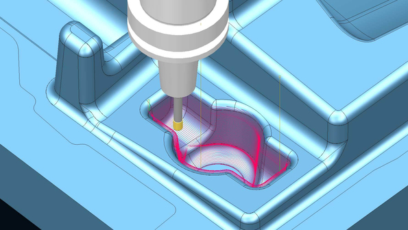 Uniform path distance with continuous Z-constant finishing.Geometries with steep flank surfaces, straight bottom surfaces and entrance and exit radii – like ribs and slots – can now be machined automatically and with a uniform step and 3-axis Z-constant machining with the "Finishing surfaces" function – without retract movements, without extra design effort and at outstanding quality.
CAM – Lathe
Turning with convenient cutting off of the part
Parts can be cut off from bar stock with a special function for automated machining on lathes or turning-milling centers. You can quickly and easily define the optimal cutting conditions for feed rate and speed on material exit. You can easily cut the part off straight or finish its contour at the same time without having to design an auxiliary geometry. You can deburr the part and turn the bar side flat during cutoff. This allows you to immediately manufacture the next part with the bar stock. The cut-off part can be transferred to the second spindle or taken up by the part gripper/catcher – with automatic control and reliable simulation.
CAM – Machine technology
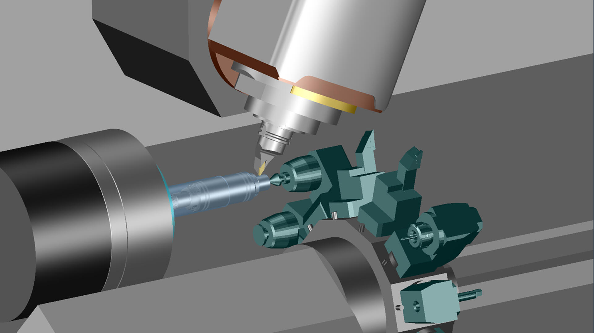
Improved support for multi-channel machine tools
 Optimal utilization of multi-channel machine centers.
This innovation is especially advantageous for manufacturing companies that rely on combined turning/milling operations, especially if the components to be machined have a high milling fraction: Tebis can now be used to program toolpaths for sequential processing on machines with multiple tool and component holders. The individual steps – such as milling with a milling head or turret, stabilizing with a centering tip or clamping with a sub spindle – can be combined in any way. All tool and component holders are stored in the virtual Tebis process libraries: These can be interchanged quickly and flexibly in programming. As always in Tebis, all system components are fully accounted for in collision checking and simulation. Programming is as easy as can be, following Tebis's stringent and proven programming logic. Tebis automatically generates NC code for any machines and supports all control-specific program structures, such as Gildemeister structure programs.
CAM – Job planning
Complete collision control with material removal simulation