

-
CAD surface quality
Automatically and manually optimizing the quality of CAD surface models
CAD surface quality results from the algorithmic properties of the CAD systems used, from the design history and from conversion processes via interfaces. CAD data with qualitative deficiencies often has to be imported and further processed in order to manufacture molds and dies. In addition to curvature, the most important evaluation criteria for CAD free-form surfaces include gaps and overlaps between the individual surfaces, polynomial degree and the number of surface segments as well as the layout of the surfaces in the overall topology. CAD surface quality can be improved in Tebis with little time and effort, which allows for better processing of the CAD data in design and manufacturing and its transfer to other CAD systems. This is realized with both automatic and manual optimization of the surfaces and results in quality up to class A.
Greater convenience and subsequent design activitiesBetter manufactured services with shorter machine run timesSimple data transfer to other CAD systemsAnalysis functions
Detection of qualitative weaknesses
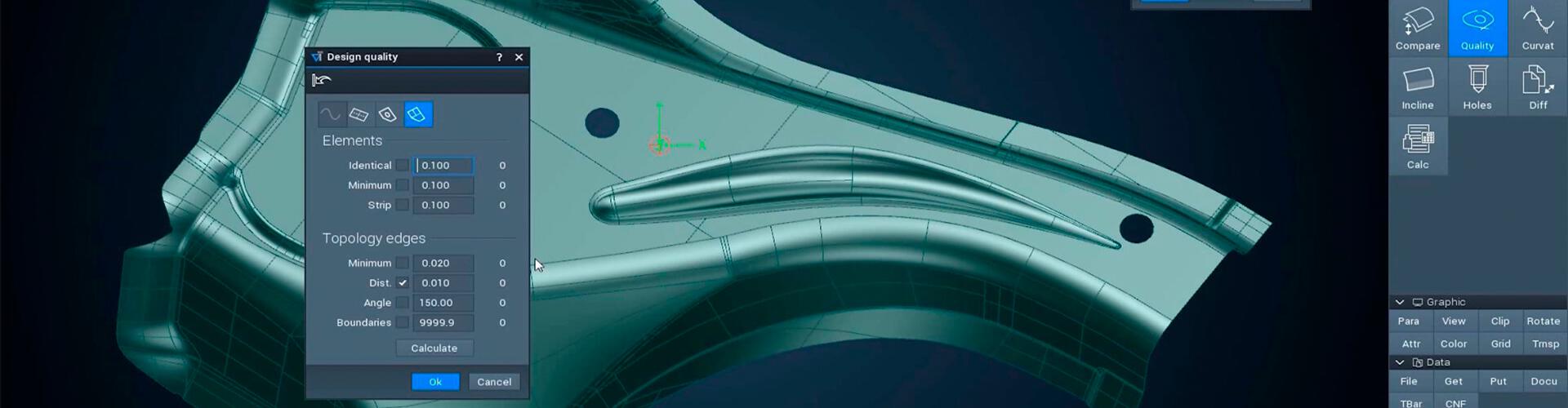
The quality analysis shows the location of problem areas in the part at a glance. This allows examination of curves, surfaces and composite surfaces (topologies).
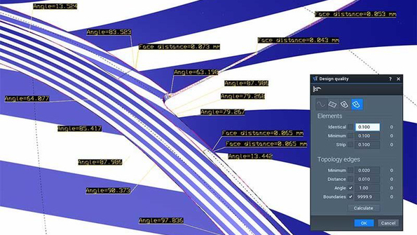 In these examples, the quality analysis shows where there are gaps that are too large and kinks between the surfaces.
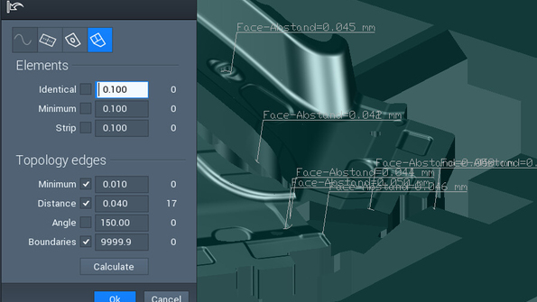
Repair at the click of a button
Easy repairing of the majority of problem areas in surface models
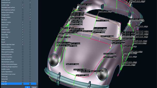
Automatic surface optimization in Tebis reduces the number of surface patches completely automatically. It also detects gaps and overlaps between individual surfaces and corrects these completely automatically to form a watertight surface model. It detects areas with high risk points in the surface layout, including kinks, trimmed surfaces with excessively large base surfaces, micro-segmented curves and surfaces. These CAD models can lead to problems later in the design and manufacturing processes. Tebis also corrects these areas in CAD surfaces automatically, which improves CAD surface quality. The result can be seen in a preview before actual execution.
Tebis detects all impermissibly large gaps between the individual surfaces and closes them completely automatically with a specifiable tolerance.Improving surface layout
Manually improving layout structures of surface models
Tebis has functions for surface design pros for handling base surfaces and N-corner surfaces, removing triangle surfaces, creating logical surface structures and much more.
 Recognize unnatural areas at the click of a button
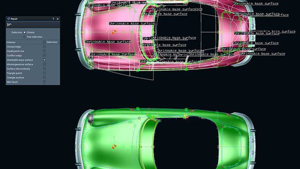 Reduce areas that are too large at the click of a button
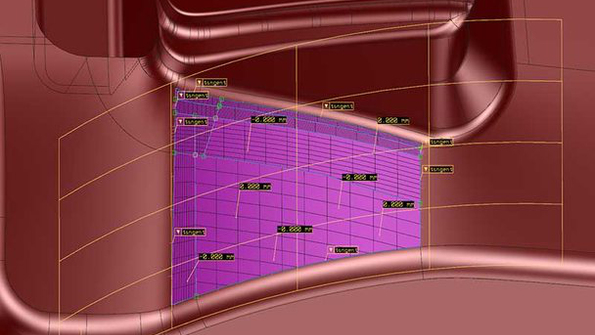 Replace the fissured surface layout with an approximation surface at the click of a button
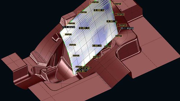 Combine several square surfaces in a single square surface with the click of a button
Class-A quality
Bringing surface models to Class-A level
Experienced surface designers can use the functions for converting curves and base surfaces to Class A in order to quickly create surfaces with reflections in harmony with all adjacent surfaces. The optimized surfaces always remain within the range of an adjustable distance tolerance from the original surfaces. The optimization of the surface models works independent of the origin of the surface data.
 For large base surfaces, the designer uses parameters to adjust the curvature transitions between the surface segments of the large carrier surface and receives visual feedback in the form of colors indicating how far the optimized surface deviates from the original.
 Designers are supported by analysis functions like zebra shading, curvature combs and control polygons. They can detect undesirable surface kinks and wavy surfaces due to incorrectly selected surface parameters, including excessive segmentation and unsuitable polynomial degrees.
For a model of medium complexity, developing high-quality CAD design surfaces for the outer skin of a vehicle now takes roughly 50 hours. (Previously, it took about twice the time.)
BWM Group-Design


