New features in Tebis 4.1
Full of features
CAD – parametric design
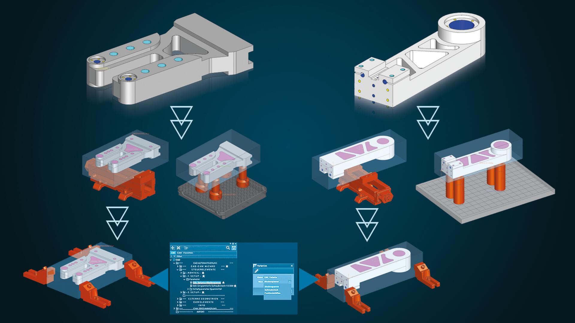
Faster preparation for manufacturing: Highly automated, flexible preparation of CAM programming with parametric CAD templates
Every imported data set must be prepared for CAM programming in design. This usually takes many individual work steps: Bores for clamping systems must be placed, tilt axis systems defined, fill surfaces designed, blanks created, connection points for setups generated, clamping devices positioned and retract planes defined. These many individual steps can be highly automated in Tebis using parametric CAD templates. These templates can be extended as needed and can be adapted to meet customer-specific requirements. Users can still be highly flexible: Changes – like selecting a different setup system – can now be directly and conveniently controlled via the user parameters in the object tree.
Parametric template technology and the proven Tebis CAM template technology for automated NC programming go hand in hand: They both contain the company's own manufacturing expertise in CAD and for CAM. CAD and CAM templates enable faster and more efficient manufacturing, and they ensure standards and uniform quality. Companies can be less dependent on the expertise of individual specialists, and new employees will get up to speed more quickly and start contributing productively to the company's success in the shortest possible time.
The parametric CAD functions are included in the Tebis CAD base model.
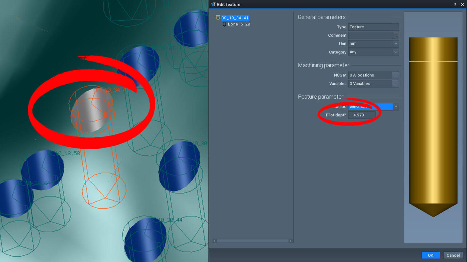
Quickly and easily create holes and pockets
The bores and pockets can be subtracted from the component with just a few mouse clicks and can later be adjusted at any time.
CAD – Electrode design
Quickly and reliably design electrodes
In addition, multiple geometrically identical electrodes can be automatically created and combined in an electrode family. For example, if you need geometrically identical electrodes with different spark gaps for roughing and finishing, this can now be very easily realized with a click of your mouse.
Practical filtering also ensures that the appropriate blank and holder for the electrode are selected. The blank is automatically oriented to the burn surfaces.
Manufacturing and measuring programs can also be managed through the structure tree. Electrode information is documented and transferred.
CAD – Active surface design
Precise results when trimming deep-drawing and bending parts
Multiple calculation modes cover different use cases.
CAD – Reverse engineering
More control: Create CAD surfaces more precisely
Tebis 4.1 solves this problem. The new G0 loop radius can be used to assign an edge the special properties that the boundary curve takes precedence in approximating the surface. To do this, simply place a loop (red) around the continuous edges of the affected facet and specify the size – either predefined as the same size everywhere or manually adjustable using individual drag arrows. Tebis then immediately displays the change in the CAD surface for optimal surface quality.
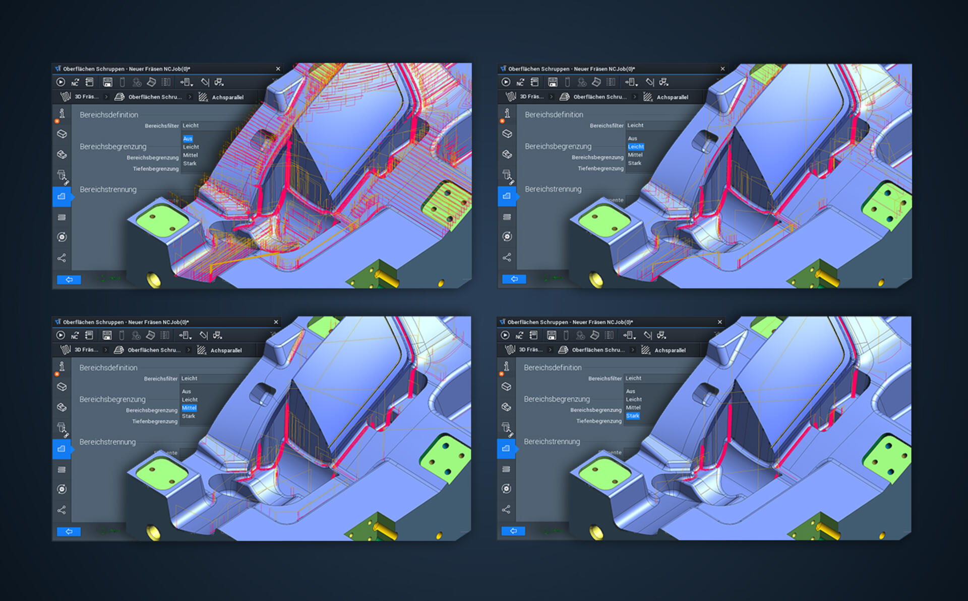
CAM – Automation
Faster programming thanks to improved NCJob technology
Take advantage of the opportunity to automatically apply interactively defined milling areas from previous NCJobs in milling – in this way you reduce manual intervention in CAM programming and calculate entire NCJob sequences at once. CAM programming is also considerably simplified – you can easily manage combined machining operations in an end-to-end CAM template.
And you can avoid issues such as superfluous calculation times by conveniently calculating multiple NCJobs simultaneously up to "Areas calculated" or "Sorting executed" status.
Quickly and easily change machining sequence
This is how the machining sequence can also be modified for existing feature groups.
Flexible NC programs with bore patterns
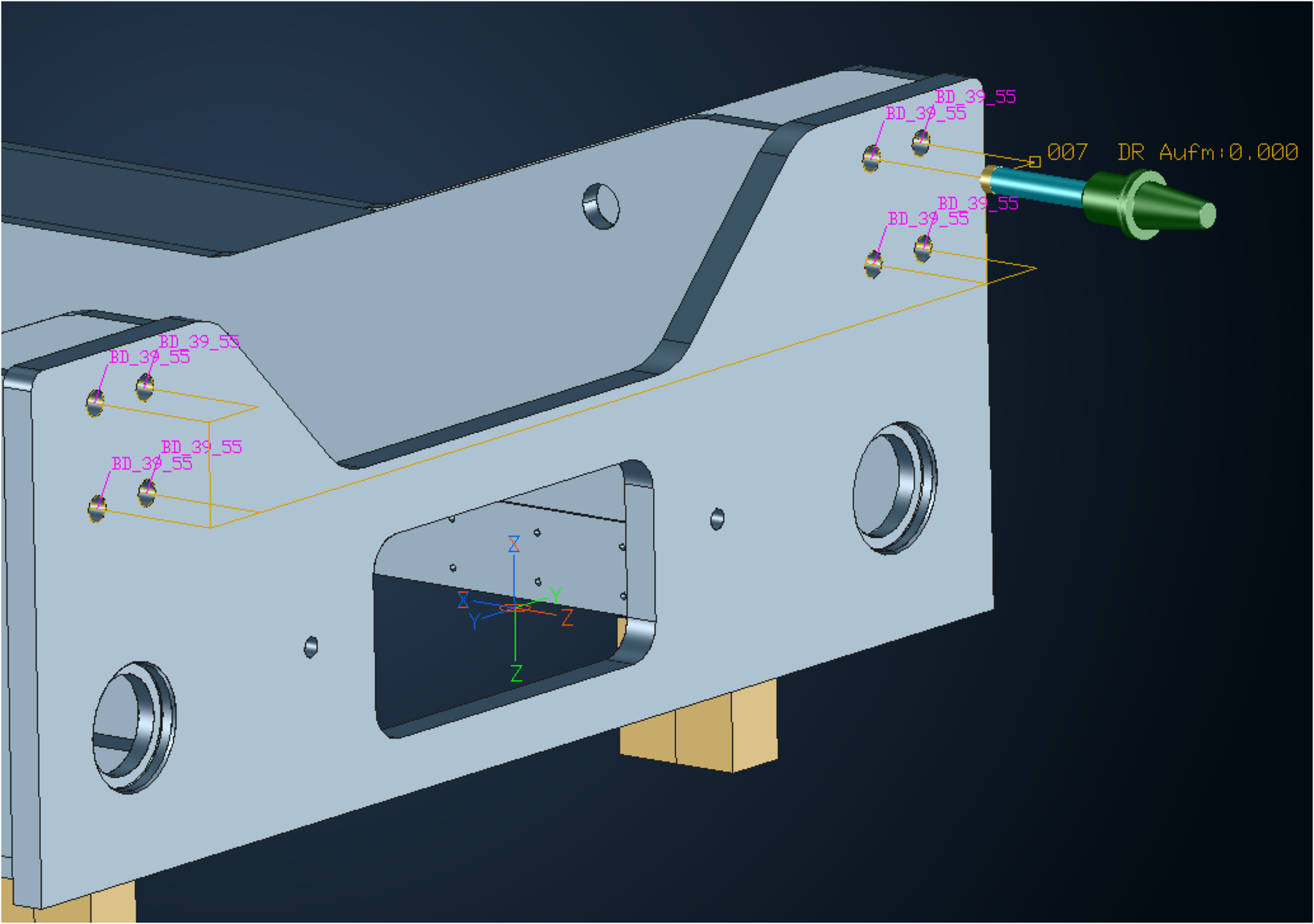
Automatically detect spot face depth
CAM – Drilling
Flexibly use special cutters

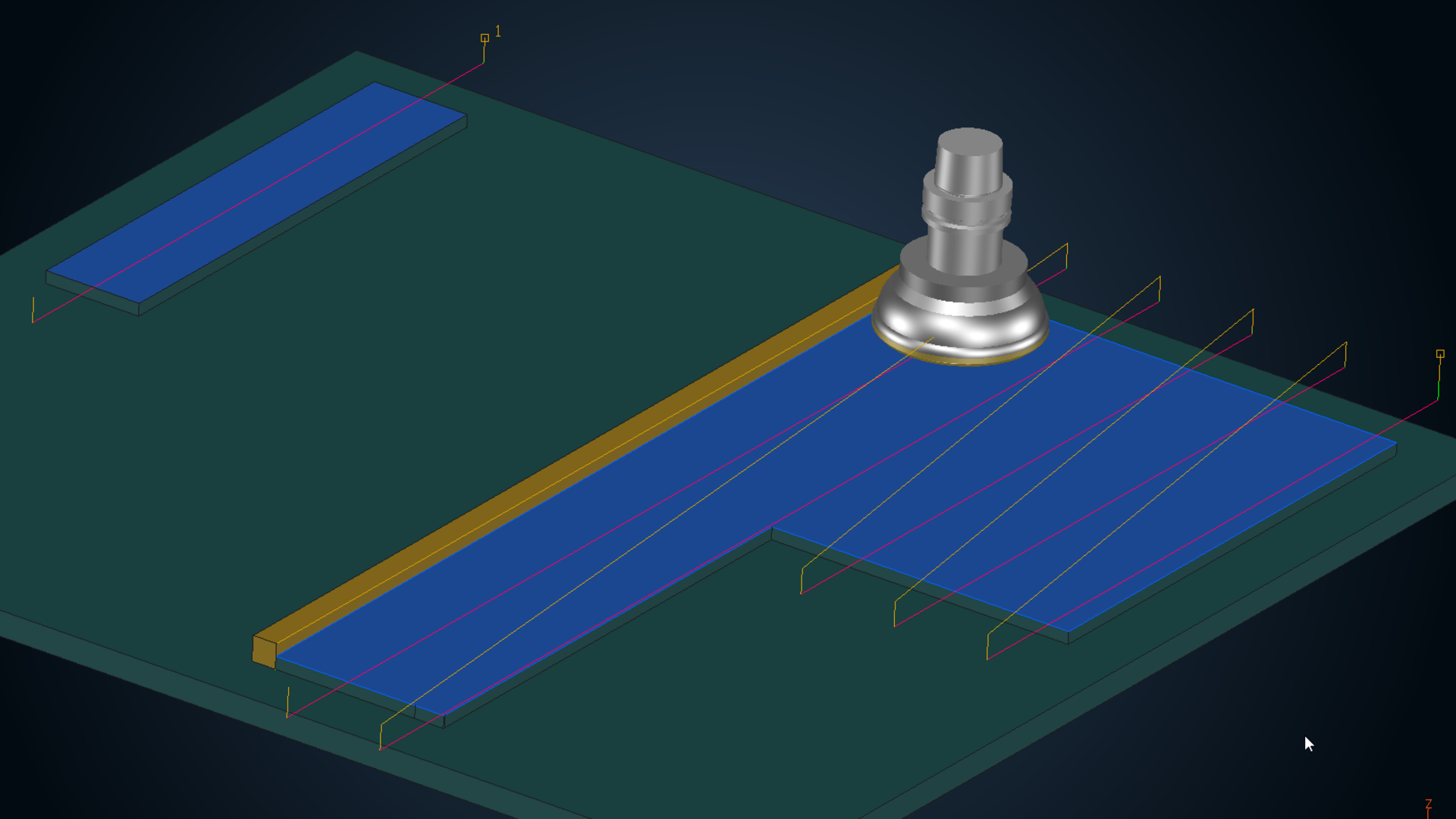
Quickly and conveniently drill multiple sections
The "Drilling in sections" function replaces the previous "Create toolpath for deep bores" function (MDEEP).
This function is also appropriate for manufacturing welded frames that often require fits to be created in multiple plates that have large free spaces between them. It can also be reasonably implemented in unit construction: for example, if sections with material and gap areas alternate in bearing guides.
CAM – Milling
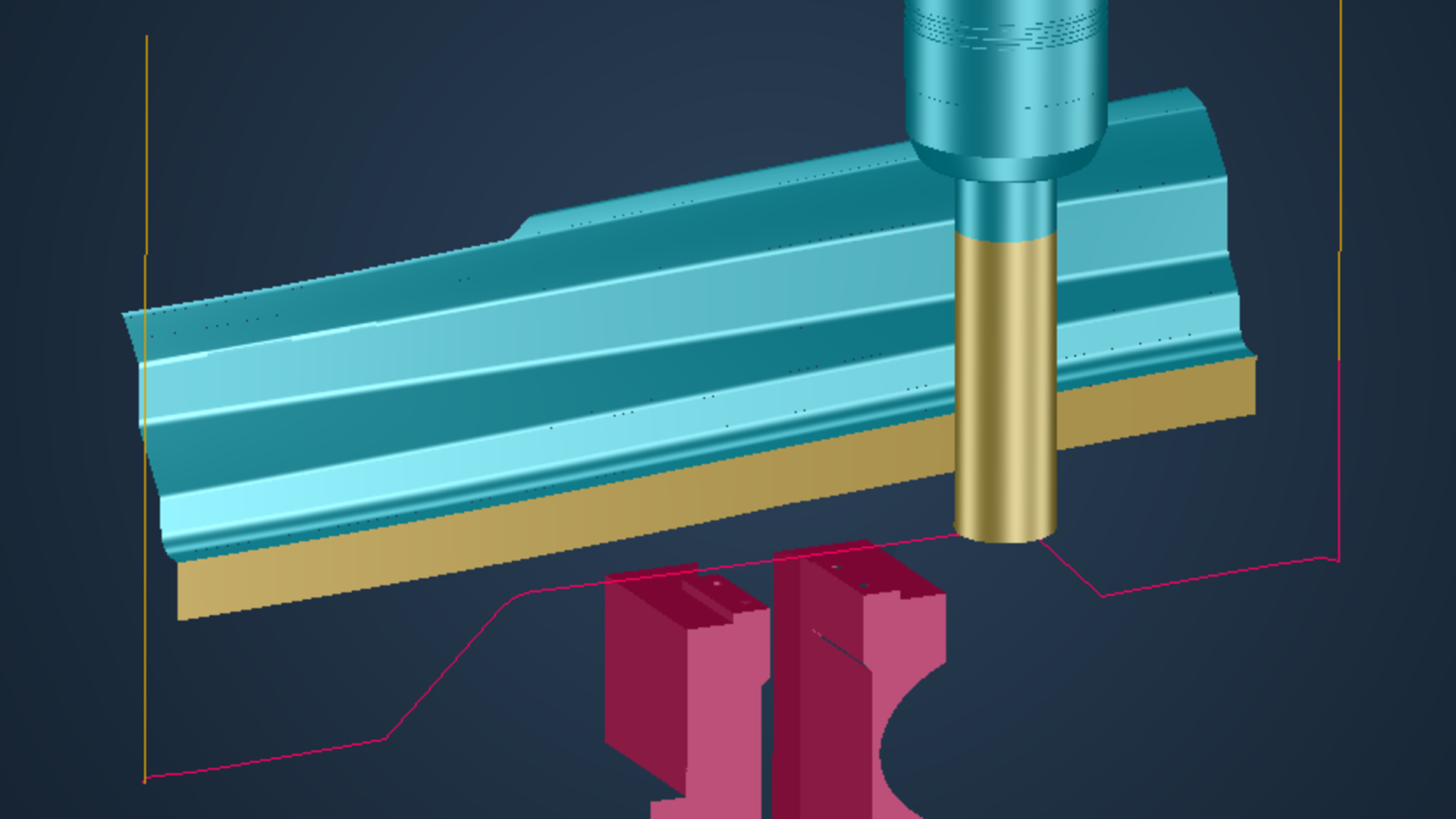
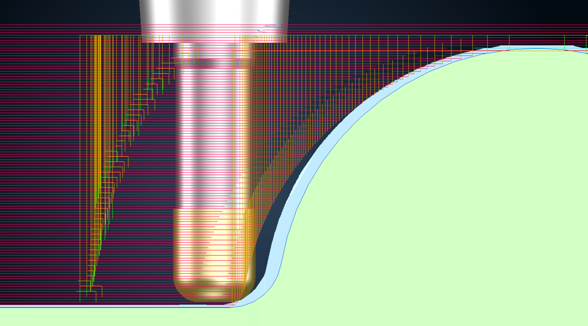
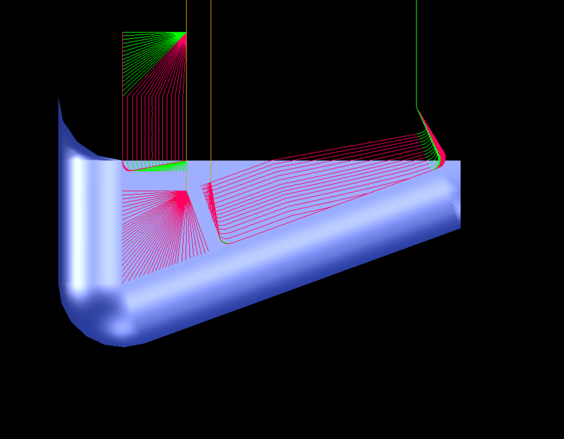
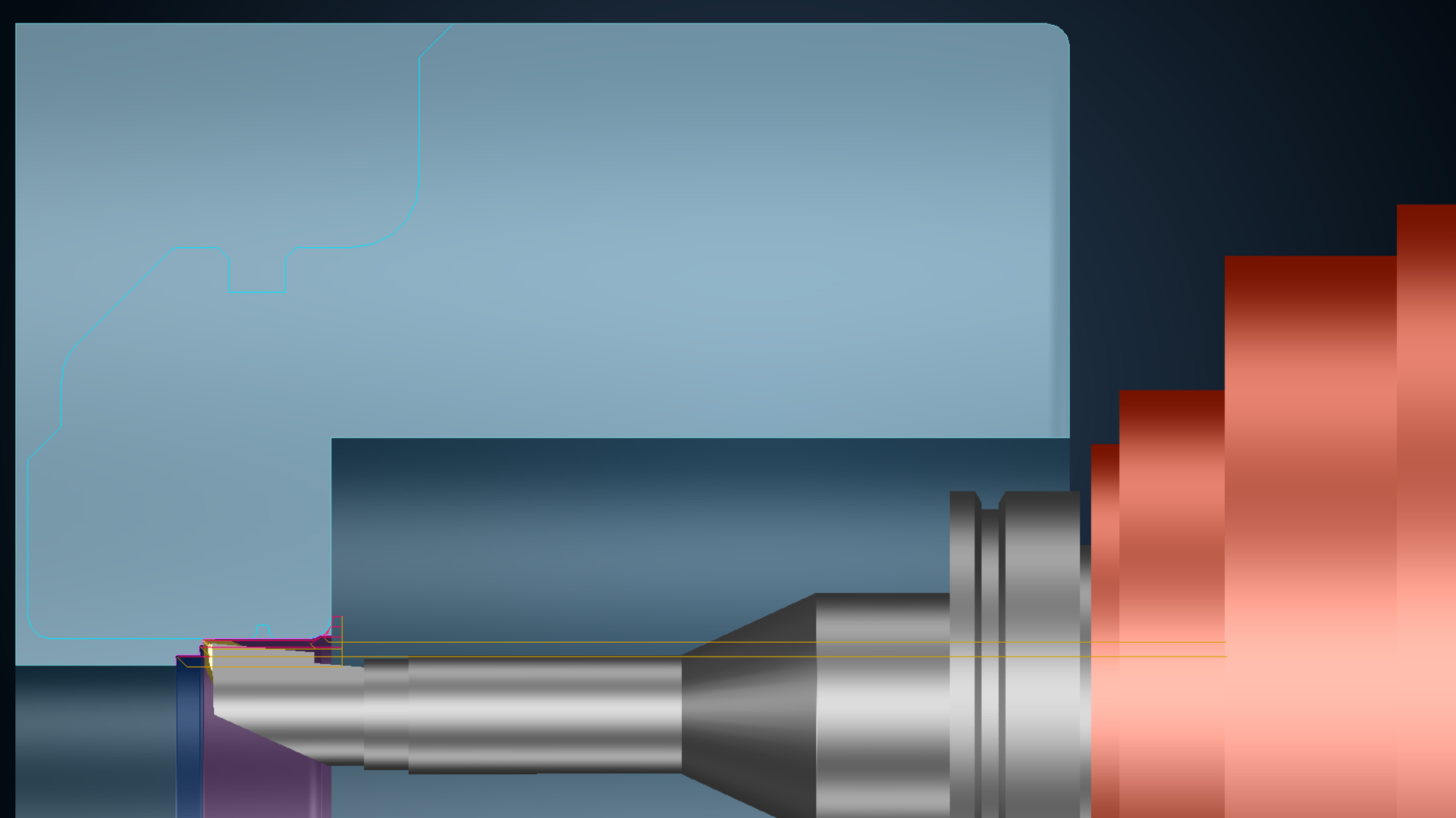
Optimal cutting conditions for roughing rotationally symmetrical parts
A real plus for combined turning/milling operations: In addition to cylindrical parts, tapered parts like screw conveyors can now also be machined with high efficiency. The tool first roughs the part to the maximum possible depth with a low stepover and large downfeed in a single pass, and it then machines the residual stock from bottom to top at a smaller cutting depth – and precisely to the stock allowance. This procedure reduces tool wear and ensures a high material removal rate on the machine. The user programs the final finishing operation very conveniently with a special function: Only the strategy is replaced – the system does the rest.
Safely manufacture external threads
Efficiently machine planar areas
Prevent minimal residual stock areas in roughing
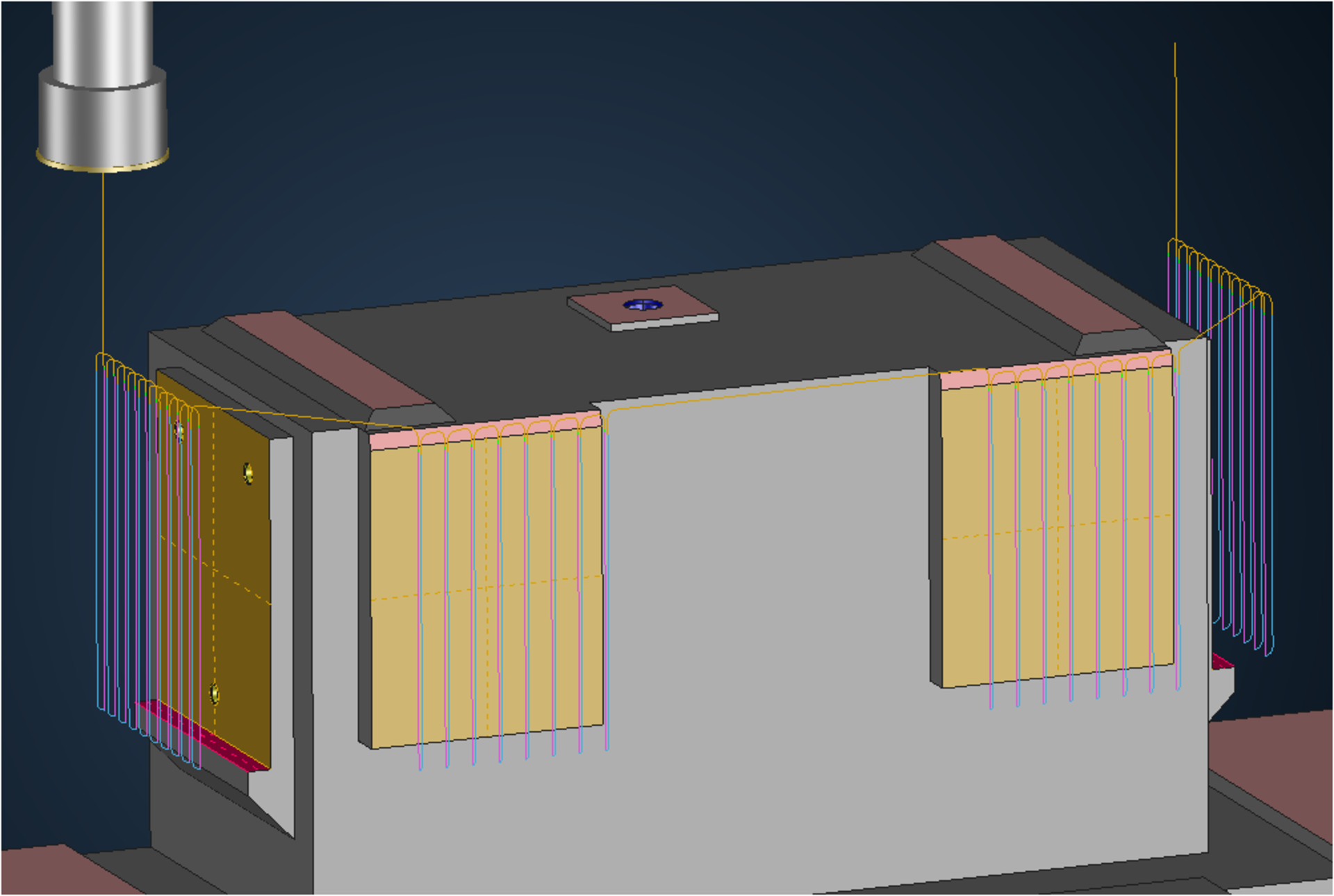
Reliable milling by accounting for the machine head
You benefit from greater process safety and enjoy tremendous time savings: Without automatic area reduction, you have to manually correct the collision after calculation and then recalculate the machining operation. With area reduction, you can use the shortest tools for every milling job, ensuring optimal cutting conditions.
Machine planar surfaces more efficiently
Finish contours with radius correction with downward machining
Contour machining with automatic avoidance
Faster completion with separate offset values
Best milling results with circle segment milling cutters
Continuous, automated 3-axis finishing of flank surfaces, transition areas and bottom surfaces with no offset

Quickly and reliably remachine fillets
Best surface quality with 3to5-axis machining
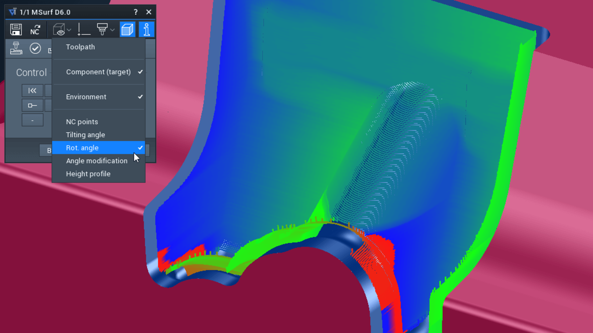
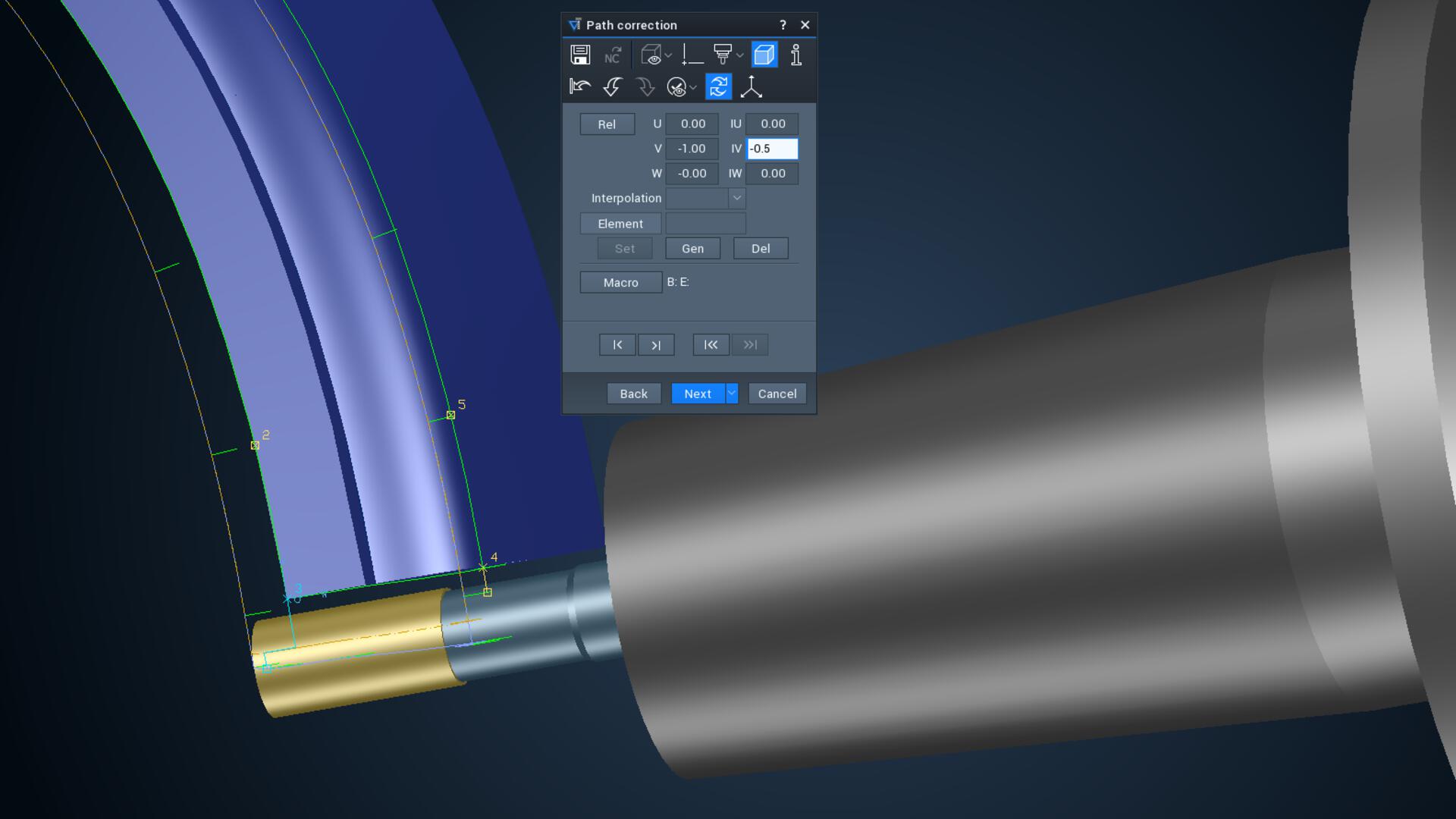
Targeted control of tool movements in 3to5ax machining operations
The "Interpolate vectors" option is useful for avoiding potential collisions with the machine head: for example, those detected during the NC calculation: Select any number of designed linear curves as vectors. These determine the tool direction and traverse movements. The system automatically interpolates between adjacent vectors.
In the "Plumb element" option, selected guide elements such as axis systems, points, curves, surfaces, topologies or meshes are used to specify the tool tilt direction and traverse movements. These plumb elements always intersect with the tool axis. This option is especially recommended if better results can be achieved with 5-axis simultaneous machining than with 3+2-axis movements due to the surface shape.
In both options, you can select between fixed and variable tilting angles around the tilt axis. They can also be combined with automatic avoidance movements at any time.
CAM – Lathe
Turning with convenient cutting off of the part
Parts can be cut off from bar stock with a special function for automated machining on lathes or turning-milling centers. You can quickly and easily define the optimal cutting conditions for feed rate and speed on material exit. You can easily cut the part off straight or finish its contour at the same time without having to design any auxiliary geometry. You can deburr the part and turn the bar side flat during cutoff. In this way you can immediately manufacture the next part with the bar stock. The cut off part can be transferred to the second spindle or taken by the part gripper/catcher – automatically controlled and reliably simulated.
Improved cutting data management for turning tools
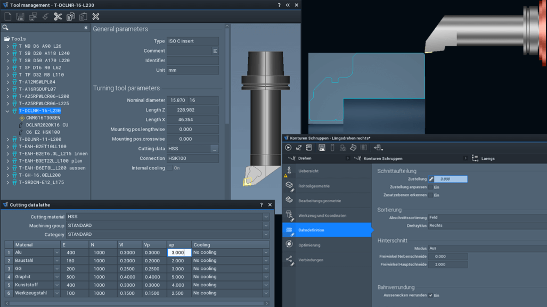
Reliable turning calculations with the tool carrier
CAM – Machine technology
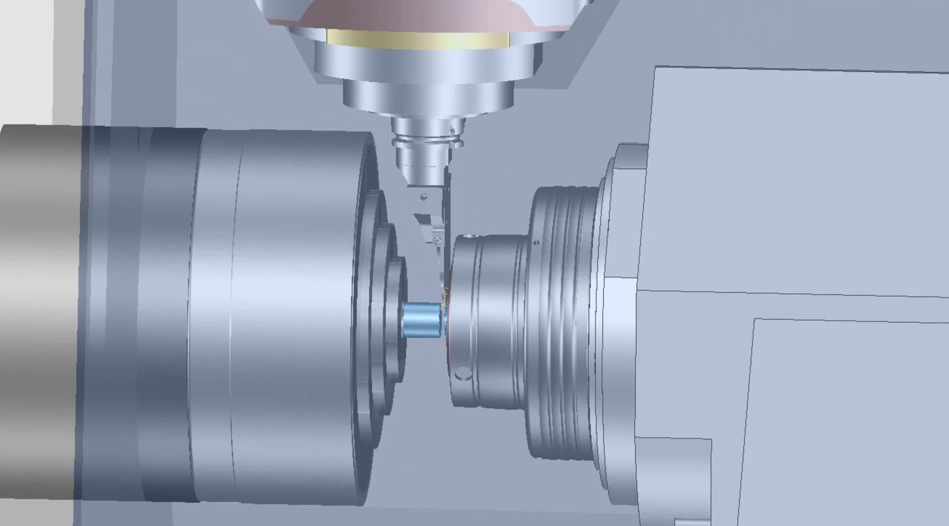
Improved support for multi-channel machine tools
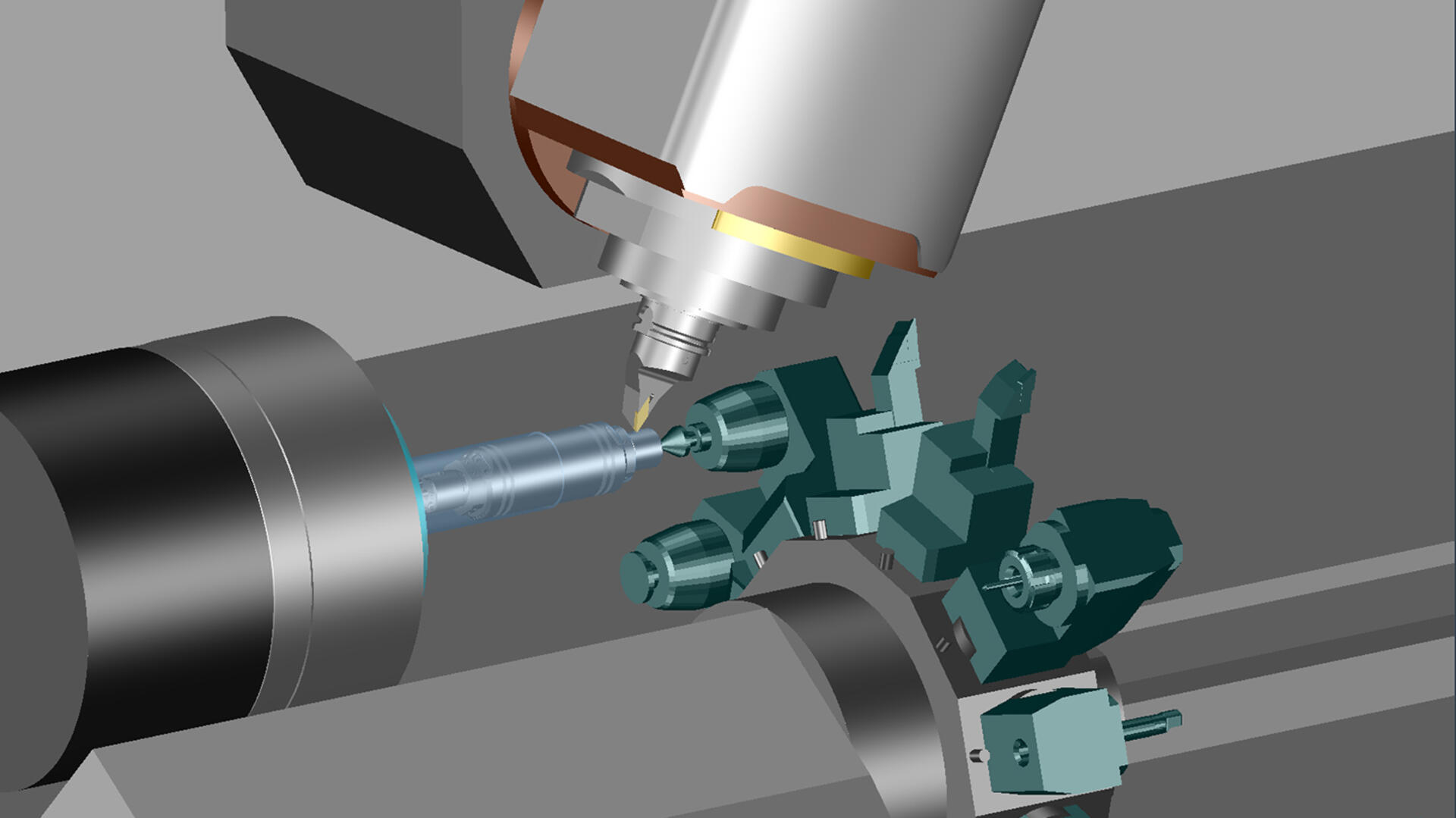
This innovation is especially advantageous for manufacturing companies that rely on combined turning/milling operations, especially if the components to be machined have a high milling fraction: Tebis can now be used to program toolpaths for sequential processing on machines with multiple tool and component holders. The individual steps – such as milling with a milling head or turret, stabilizing with a centering tip or clamping with a sub spindle – can be combined in any way. All tool and component holders are stored in the virtual Tebis process libraries: These can be interchanged quickly and flexibly in programming. As always in Tebis, all system components are fully accounted for in collision checking and simulation. Programming is as easy as can be, following Tebis's stringent and proven programming logic. Tebis automatically generates NC code for any machines and supports all control-specific program structures, such as Gildemeister structure programs.
Convenient part transfer between main and sub spindles
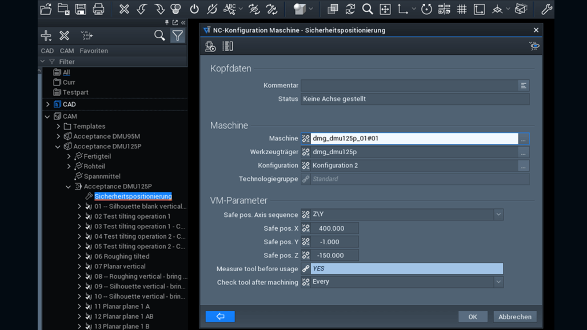
Flexibly control machining centers
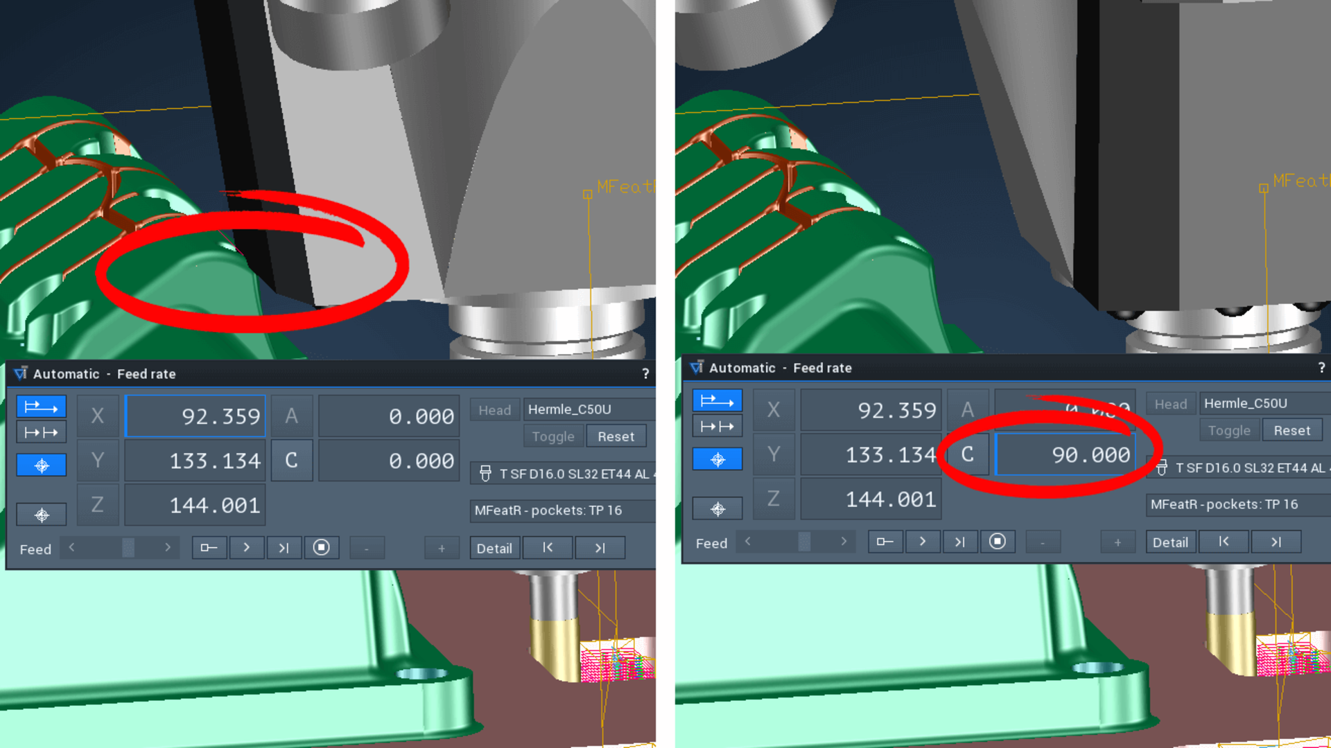
More machining options with free-rotation axes
CAQ – Measure
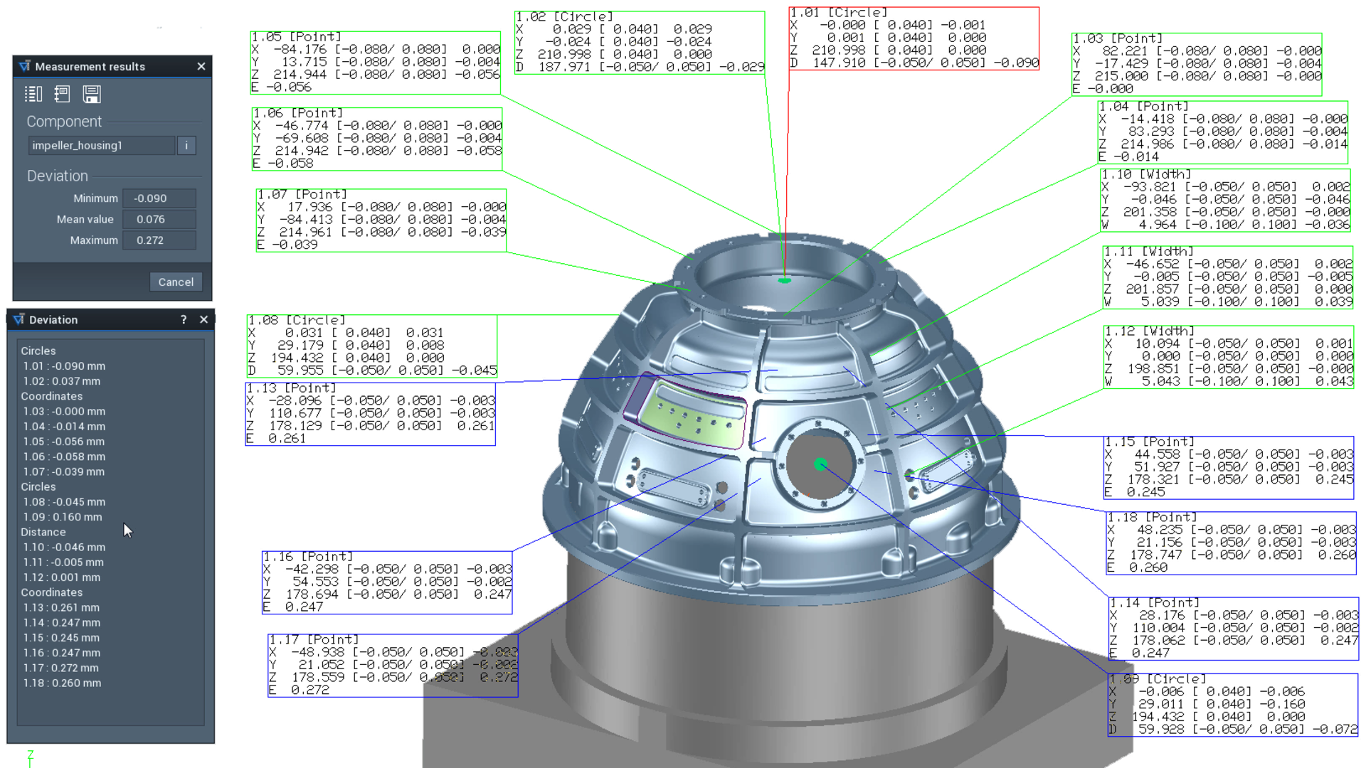
Increased productivity, thanks to measurement integrated in the process
Clearly display and document measurement results
CAM – Job planning
Complete collision control with material removal simulation
Transform toolpaths with process safety
CAM – Laser cutting and trimming
Simple incremental movement of paths